3501 #2: Rendering Geometry
Assignment 2: Rendering Geometry
Due date: Wednesday, Sept 29
This assignment is about traditional real-time rendering, where objects are
described by their geometry. In XNA, an Effect is needed to render geometry;
we will learn to use the BasicEffect. This assignment involves creating a
simple model of your own design and rendering it with the BasicEffect.
Potential Problems
Two possible sources of problems for your model are:
- Backface culling. By default, XNA will only draw triangles whose
vertices are in clockwise order, as seen from the camera. If you want
to draw all triangles, including "backwards" ones, add the line:
graphics.GraphicsDevice.RenderState.Cullmode = Cullmode.None;
- Frustum culling. Make sure that all the vertices you want to
see are in front of the near clipping plane and behind the far
clipping plane. (That is: close enough to the camera, but not too close,
and in front of the camera.)
Part 1: setup
- Create view, projection, and world matrix transforms.
- Create and initialize a BasicEffect. This means setting the View,
Projection, and World components of the BasicEffect, plus enabling
VertexColorEnabled, and committing the changes with .CommitChanges().
- Create a VertexDeclaration. Set the VertexDeclaration of your
GraphicsDevice to the new VertexDeclaration.
- In the Draw method, write the code to go through all Techniques and Passes
of the BasicEffect.
- Pause and make sure the code runs (although it won't actually draw
anything yet).
Part 2: your own model
You should next design your own model to be displayed. This will involve
both vertex placement and details of how the vertices will define the
primitives (in this case, triangles or triangle strips).
Then, decide on how it should be colored -- you can (and must) assign
a color to each vertex. Try to assign distinct colors to every vertex
so that it is clear from looking at this image where the vertices are.
This might help in debugging, too.
You ought to place your vertices in an array, because that will make
the drawing part easier. In fact, you may want to use multiple arrays
for distinct pieces of the model.
Use vertex type VertexPositionColor: each of
your vertices will have a position value (its location) and a color value
(such as Color.White).
Be sure to place the camera in such a way that your model can be seen.
A simple strategy is to put the model at the origin (0,0,0) and
pull the camera back along the Z axis (so that its position is (0,0,10), say).
Then have the camera look at (0,0,0).
Finally, build your model. You are going to create a simple model of
a cannon.
The cannon should have (at least)
two components:
a base part and a barrel part.
The cannon should be
built in full 3D -- i.e., the barrel should have four sides (at least),
and the base should have four sides (at least) and a top.
The barrel needn't have a top, but it can if you think it will look better.
A possible workflow is as follows:
- Draw a diagram of your cannon on paper. You may want to use the
drafting technique of drawing a top, front, and side view.
- Identify the vertices and break the model down into primitives
(isolated triangles or triangle strips).
- Decide on locations (and colors) for your vertices and type the data
into your vertex arrays.
- Add suitable commands (probably graphics.DrawUserPrimitives)
to the Draw method so that your arrays will be drawn.
- Test that an appropriately colored model appears on the screen when
you run your program.
Part 3: bonus
For a bonus of up to +10%, write code that automatically creates the
vertex data for a curved geometric object, such as a sphere or cylinder.
Incorporate the resulting curved object into your cannon in some way,
say by adding wheels or having a round barrel.
Handing it in
Hand in your project using WebCT.
The easiest thing to do is to create a single zipped folder and submit
that, rather than all the individual files. It might take a while to
upload, so be prepared to take a little break while the files are in
transit.
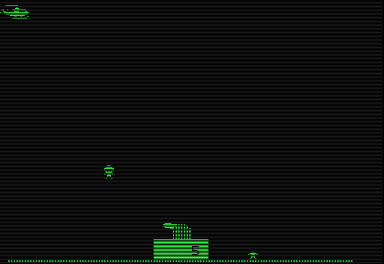
Reference art
The simple cannon of the classic game Sabotage:


